How Does ISO 5211:2023 Guide Electric Actuator Mounting?
News Details
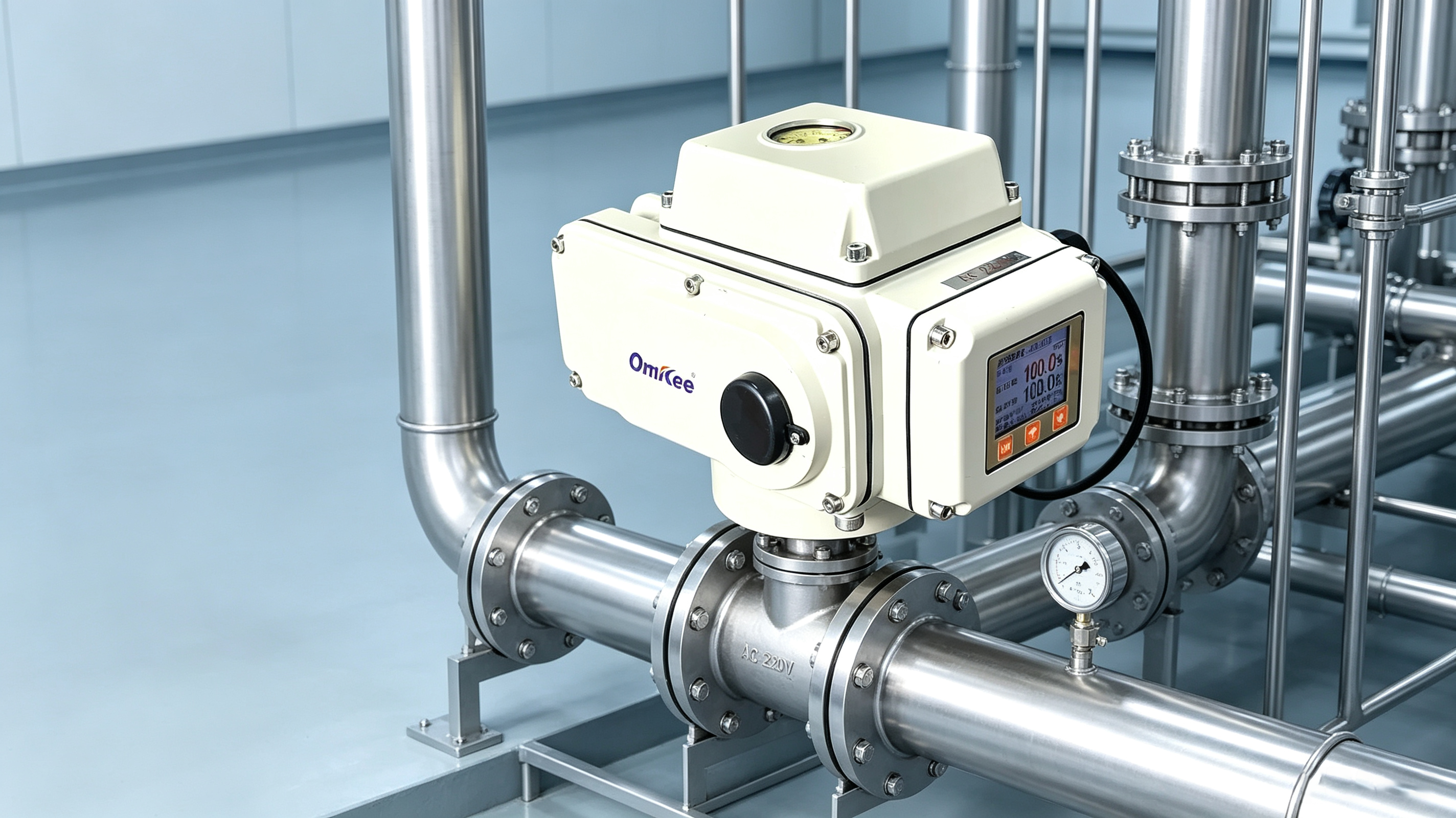
When an electric actuator is installed on a quarter-turn valve, the mechanical connection must be correct. The actuator needs to transfer torque to the valve without misalignment, interference, or excessive stress.
This is where ISO 5211:2023 becomes important. The standard defines key requirements for attaching part-turn actuators to industrial valves. It covers the mounting interface, flange dimensions, drive components, and reference torque values.
For valve manufacturers, automation engineers, and industrial buyers, understanding these requirements can make actuator selection and installation much easier.
OMKEE manufactureselectric actuators and automated valve solutions for applications including petroleum, power, and water treatment. Its product range includes compact and explosion-proof quarter-turn electric actuators.
What Is ISO 5211:2023?
ISO 5211:2023 is an international standard for part-turn actuator attachments. In simple terms, it helps define the mechanical interface between an actuator and a valve.
A part-turn actuator transmits torque to a valve through one revolution or less. This makes the standard particularly relevant to quarter-turn valves such as ball valves and butterfly valves.
The standard mainly addresses:
-
Mounting flange dimensions
-
Bolt and hole arrangements
-
Actuator drive dimensions
-
Valve drive dimensions
-
Reference torque values
-
Clearance between driving and driven parts
However, ISO 5211 does not select the complete actuator for a specific valve. The valve manufacturer, actuator manufacturer, and purchaser still need to confirm application requirements.
What Are ISO 5211 Mounting Flanges?
The mounting flange creates the mechanical connection between the actuator and valve.
ISO 5211:2023 defines a series of flange types, including F03, F04, F05, F07, F10, F12, F14, F16, F25, F30, F35, F40, F48, F60, F80, and F100. Each type has defined dimensional and torque characteristics.
For example:
| Flange Type | Maximum Reference Flange Torque |
|---|---|
| F03 | 32 Nm |
| F04 | 63 Nm |
| F05 | 125 Nm |
| F07 | 250 Nm |
| F10 | 500 Nm |
| F12 | 1,000 Nm |
| F14 | 2,000 Nm |
| F16 | 4,000 Nm |
| F25 | 8,000 Nm |
| F30 | 16,000 Nm |
These values continue to increase for larger flange types, reaching 1,000,000 Nm for F100.
Importantly, these are reference maximum flange torque values under the conditions defined by the standard. They should not be treated as the required operating torque of a valve.
How Do You Read Electric Actuator Mounting Flange Sizes?
When comparing electric actuator mounting flange sizes, do not look only at the outside diameter.
The interface includes several dimensions. These can include:
-
Flange outside diameter
-
Recess or spigot diameter
-
Bolt circle diameter
-
Bolt or screw size
-
Number of mounting holes
-
Flange height
-
Drive dimensions
For instance, ISO 5211:2023 specifies F05 with a maximum flange diameter of 65 mm, a minimum d2 diameter of 35 mm, a d3 diameter of 50 mm, and four M6 mounting screws. F07 uses a 90 mm maximum flange diameter and four M8 mounting screws.
Therefore, two actuators with similar outside dimensions may still have different mounting interfaces.
Why Is the Drive Connection Important?
The flange is only one part of the connection. The actuator must also correctly engage with the valve stem or driven component.
ISO 5211:2023 provides requirements for the actuator drive and valve-driven component. It also limits the driven component's length above the interface to help prevent interference.
Common drive arrangements include:
-
Single-key drives
-
Two-key drives
-
Parallel square drives
-
Diagonal square drives
-
Flat-head drives
-
Splined drives
So, during quarter turn actuator selection, engineers should check both the mounting flange and the drive connection.
How Should You Choose the Right ISO 5211 Electric Actuator?
A suitable ISO 5211 electric actuator should match the valve in several ways.
1. Check Valve Torque
First, determine the valve's required operating torque. Consider factors such as:
-
Breakaway torque
-
Running torque
-
Seating torque
-
Pressure conditions
-
Medium
-
Temperature
-
Safety margin
The actuator's available output torque should be suitable for the complete valve operating cycle.
2. Match the Flange
Next, check the valve's ISO 5211 flange type.
For example, if the valve uses an F07 interface, the actuator should have a compatible F07 mounting interface or an approved adapter.
3. Check the Drive
The actuator drive must match the valve stem or coupling. A correct flange with an incorrect drive connection will not create a usable installation.
4. Check the Rotation
Quarter-turn valves normally require a defined rotation, commonly 90°. However, the actual actuator travel and valve requirements should always be confirmed before installation.
What Should You Check Before Mounting?
Before installing an actuator, use a simple checklist:
-
Confirm the valve flange type.
-
Confirm actuator flange type.
-
Compare bolt-hole positions.
-
Check the drive shape and dimensions.
-
Check stem engagement depth.
-
Confirm actuator output torque.
-
Check valve operating torque.
-
Make sure there is enough clearance.
-
Confirm the actuator's rotation direction.
-
Follow the actuator manufacturer's installation instructions.
ISO 5211 specifies that mounting holes are equally spaced and positioned off-center according to the relevant flange requirements.
This helps prevent incorrect orientation during assembly.
Does ISO 5211 Apply to Every Electric Valve Actuator?
Not necessarily.
ISO 5211 focuses on the attachment of part-turn actuators to industrial valves. It does not cover every aspect of an actuator or every type of valve automation system. For example, the attachment of an intermediate support to the valve is outside the scope of the standard.
Also, electrical specifications such as voltage, control signals, wiring, protection class, and communication protocols must be evaluated separately.
For example, OMKEE offers quarter-turn electric actuators with different power and control configurations, including 24 V DC and AC-powered models.
What Does ISO 5211 Mean for B2B Valve Buyers?
For distributors and industrial automation buyers, ISO 5211 can make product selection more systematic.
Instead of comparing actuators only by output torque or motor power, buyers can also compare the mechanical interface.
A good purchasing specification should include:
| Specification | Example Requirement |
|---|---|
| Valve type | Ball valve / butterfly valve |
| Actuator type | Electric quarter-turn |
| Flange | ISO 5211 F05 / F07 / F10 |
| Drive | Square / key / other specified type |
| Output torque | Application-specific |
| Rotation | 90° or application-specific |
| Power supply | 24 V DC / 220 V AC / 380 V AC |
| Protection | Required IP rating |
| Control | On/off or modulating |
| Environment | Indoor / outdoor / hazardous area |
This approach reduces the risk of ordering an actuator that fits electrically but does not fit mechanically.
Conclusion
ISO 5211:2023 provides a common framework for connecting part-turn actuators and industrial valves. Its flange dimensions, drive requirements, and torque references make actuator selection and mounting easier to standardize.
For quarter turn actuator selection, however, the flange is only the starting point. Engineers should also check valve torque, drive dimensions, rotation, operating conditions, power supply, and control requirements.
By checking these points together, buyers can select a more suitable ISO 5211 electric actuator and create a safer, more reliable valve automation system.
For projects requiring different actuator configurations, OMKEEprovides electric actuator solutions for industrial valve automation, including compact and explosion-proof quarter-turn models.


